
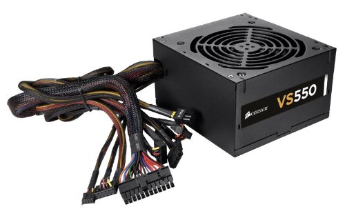
A switched-mode power supply is an electronic power supply that incorporates a switching regulator to convert electrical power efficiently. Like other power supplies, an SMPS transfers power from a DC or AC source (often mains power) to DC loads, such as a personal computer, while converting voltage and current characteristics.
Switching power supplies have high efficiency and are widely used in a variety of electronic equipment, including computers and other sensitive equipment requiring stable and efficient power supply. SMPS is also known as a switch-mode power supply or switching-mode power supply.
Computers require low voltage direct current (DC) for their working. Power supply unit of computer convert 230V alternating current (AC) supply from mains to 5 V and 12 V. The process of conversion includes reducing the mains supply voltage to a lower voltage and then transformation of AC supply to DC supply. The power supply unit also helps in control and regulation of the supply to prevent value variations and to set the output to the precise level.
Conversion to direct current for operating computers is achieved by using high frequency switching process. The ehermating voltage is switched off and on several thousand times per second to get the direct voltage. Hence the power sapply unit used is the computer system is known as Switch Mode Power Supply.
Major components of power supply unit are transformer, bridge rectifier, capacitor and voltage regulator.
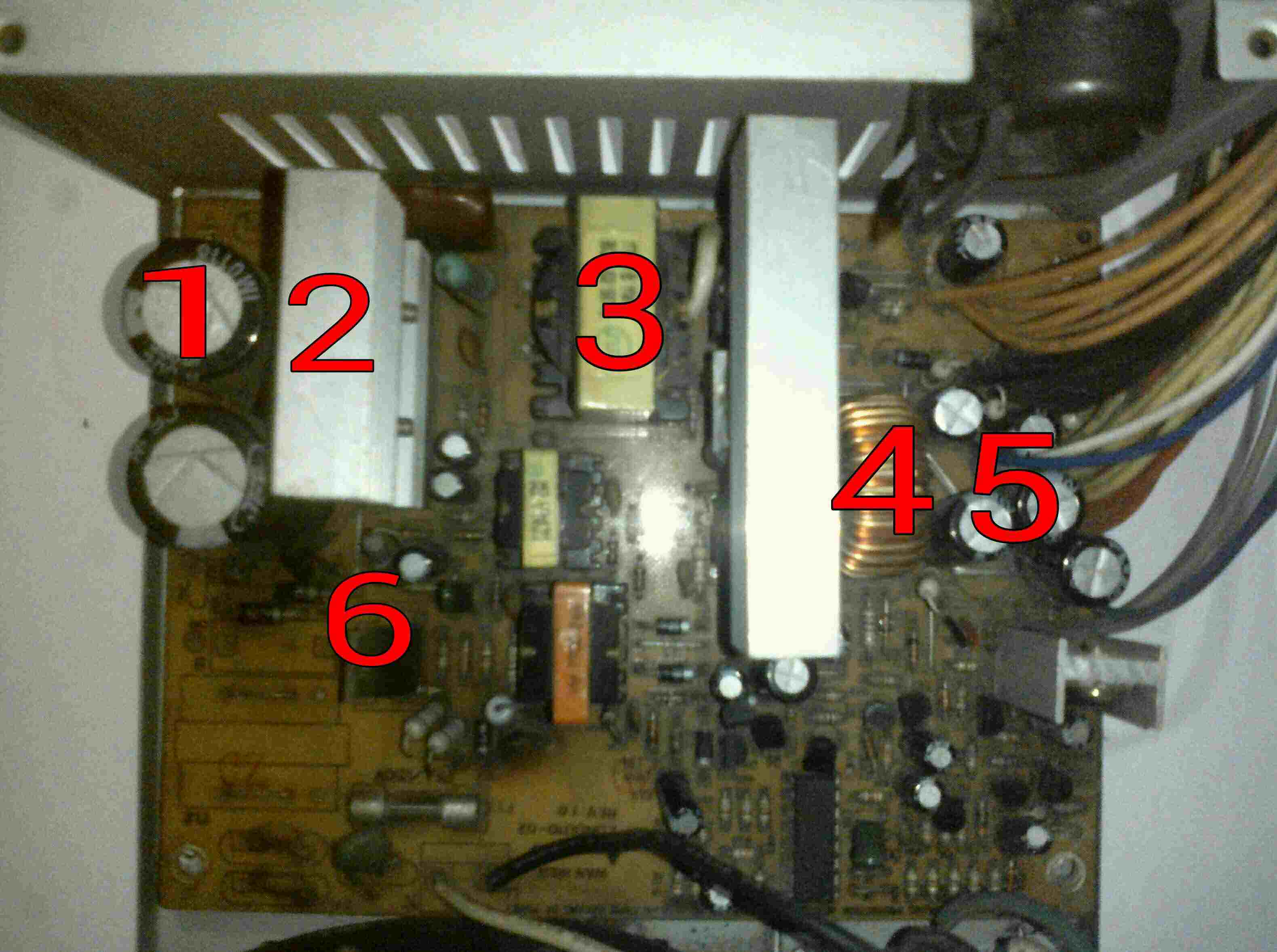
Capacitor is an electronic component that stores electric charge. The capacitor is made of 2 close conductors (usually plates) that are separated by a dielectric material. The plates accumulate electric charge when connected to power source. One plate accumulates positive charge and the other plate accumulates negative charge.
Heat Sink:Heat sinks are usually made of metal, which serves as the thermal conductor that carries heat away from the CPU and other electronic components. However, there are pros and cons to use every type of metal. First, each metal has a different level of thermal conductivity. The higher the thermal conductivity of the metal, the more efficient it is at transferring heat.
Transformer:Electrical power transformer is a static device which transforms electrical energy from one circuit to another without any direct electrical connection and with the help of mutual induction between two windings. It transforms power from one circuit to another without changing its frequency but may be in different voltage level. In the case of SMPS, transformer helps to transform 240/230 v of AC current to 5-12 v of DC current.
Output Filter Coil:In electronics, a choke is an inductor used to block higher-frequency alternating current (AC) in an electrical circuit, while passing lower-frequency or direct current (DC). A choke usually consists of a coil of insulated wire often wound on a magnetic core, although some consist of a doughnut-shaped "bead" of ferrite material strung on a wire.
Output Folder Capacitor:Filter capacitors reduce the amount of ripple voltage to a level that is acceptable. It should be noted that resistors and inductors can be combined with the capacitors to form filter networks. Here we will concentrate on capacitive filters only. In a filter circuit the capacitor is charged to the peak of the rectified input voltage during the positive portion of the input. When the input goes negative, the capacitor begins to discharge into the load. The rate of discharge is determined by the RC time constant formed by the capacitor and the load's resistance.�
Voltage Regulator:A voltage regulator is designed to automatically maintain a constant voltage level. A voltage regulator may use a simple feed-forward design or may include negative feedback. It may use an electromechanical mechanism, or electronic components. Depending on the design, it may be used to regulate one or more AC or DC voltages.
We can see 2x2 pins layout having 12v power output which provide enough power to the processor. This connector is connected near the processor of motherboard. The 2x10 pin ATX power supply main connector is the largest connector of the SMPS unit. This connection provides power to different components of motherboard. The 4 pin 12 v power connectors provides power which are also known as molex connector. The computer SMPS unit usually has more than one molex connector. SATA power cable is different from traditional four pins parallel power connectots. These connectors usually are of black color and looks thin. We can find more than one one SATA connectors in modern SMPS.
Here we will discuss about different cables of SMPS and the voltage which they contain.
Main Power Cable: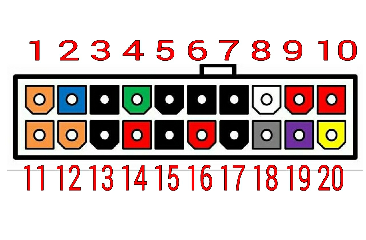
| sl no. | color | volts |
| 1,11,12 | Orange |
+3.3 |
| 2 | Blue |
-12 |
| 3,13,5,6,7,15,17 | Black | ground |
| 4 | Green |
ps-on |
| 8 | White |
-5 |
| 4,6,19,20 | Red |
+5 |
| 18 | Gray |
pg |
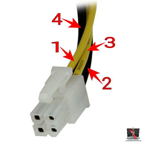
| sl no. | color | volts |
| 1,3 | Yellow |
+12 |
| 2,4 | Black | Ground |
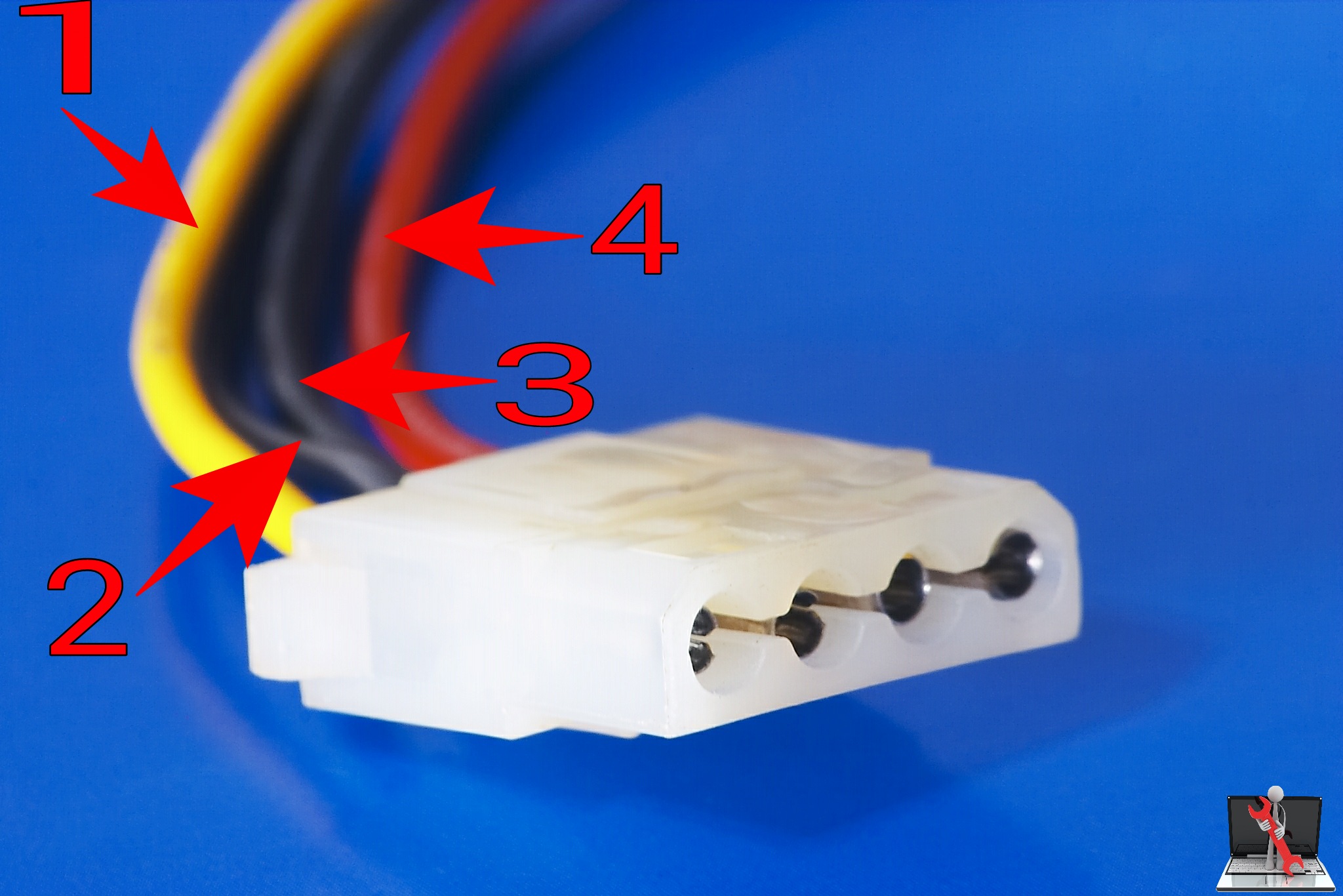
| sl no. | color | volts |
| 1 | Yellow | +12 |
| 2,3 | Black | Ground |
| 4 | Red |
+5 |
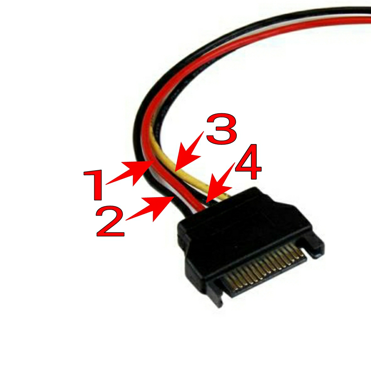
| sl no. | color | volts |
| 1 | Red |
+5 |
| 2,4 | Black | Ground |
| 3 | Yellow |
+12 |
First connect the SMPS in the computer cabinet socket that is provided for placing power supply unit.
The processor fan must be facing outside to dissipate the heat outflow.
Connect the main power cord of 20 or 24 pins on the motherboard given connector.
Connect the 4pin 12 V cord near the CPU socket on the motherboard given connector.
Connect other 4 pins Molex connectors to Hard Disk, DVD Rom and other required connectors.
At last but not the least connect the 230 V power cord from the power supply switch board to the SMPS.